


Power Control of Parallel Inverters in Microgrid
- University of Food Industry, Ho Chi Minh City, Vietnam
Abstract
In Microgrid, inverters are connected in parallel to improve efficiency, increase transmission capacity, easily repair, maintain, and facilitate Microgrid structure change. However, in stand-alone mode the inverters must be controlled to power-sharing by the ratio of their rated power, because if the current supplied to the load is not be shared by the ratio of the rated power of the inverters, it will be a guide to an overload, or reactive current circulating in the inverters, which will lead to heating and even damage to the inverters. Therefore in this paper also introduces a power-sharing control method for parallel-connected inverters in the Microgrid. The proposed controller will perform the correct power sharing according to the rated power ratio of the inverters connected in parallel in Microgrid, this controller is not affected by line impedance and local loads under usual or where field cases communication bus combination is delayed or interrupted.
Introduction
Distributed generation (DG) sources are increasingly widely used. Currently, DGs are interested in many industrial fields and become one of the most interesting research directions in the energy field 1, 2, 3, 4, 5, 6, 7. Although distributed generation using wind energy, solar or diesel energy, ... are energy sources that can produce small-scale electricity, in the future, it can be seen as an alternative or complementary source for traditional electricity sources such as thermoelectricity or hydroelectricity. DGs help address the increase in global warming caused by fossil fuels.
Microgrid consists of DGs (DG1,.. DGn). Each DG includes small power generation sources (micro source): solar energy, wind, diesel,...; energy storage system and inverters.
When there is a need for grid expansion, it is difficult for conventional power systems to meet the reliability requirements and diverse needs of electricity users. Furthermore, DGs have the advantage of reducing pollution, flexible installation placement, and reducing power transmission loss. DGs can be controlled easily and are more reliable than traditional power generation sources, so microgrids play an even more important role in maintaining grid stability1, 2, 3, 4, 5, 6, 7, 8, 9. Microgrid is increasingly providing stronger and more effective support for the traditional power grid 10.
Microgrid and the small power generators are connected on the DC bus, this type of configuration reduces the number of inverters. The energy storage battery helps to stabilize the input voltage of the inverter. Because Microgrid has a common feature that often supplies electricity to remote areas where there is no public power grid, so Microgrid often includes local loads located near areas of energy source (close to the output of the inverter) and concentrated loads (public loads) located in the center of the load and a few hundred meters away from energy sources, usually located at the common AC bus, as can be shown in Figure 1.

Configuration of Microgrid in DC style
Microgrid consists of DGs that are communicated with the grid through inverters, Microgrid is designed so that it can work flexibly in two modes: islanded and grid connection1, 2, 3, 4, 5, 6.
In stand-alone mode, the Microgrid has two important tasks: power sharing between inverters connected in parallel and to maintain voltage and frequency stability.
The inverters in the microgrid can have the same or different rated capacity, and the impedance of the line connecting the inverter to the point of common coupling (PCC) can also be the same or different. Furthermore, in the microgrid there are also nonlinear and unbalanced loads. This fact will cause balanced currents to flow between the inverters, which can damage the inverters 3, 4, 5, 6, 7, 8, 9, 10, 11, 12, 13. The circulating current flowing between the inverters can be illustrated as shown in Figure 2.
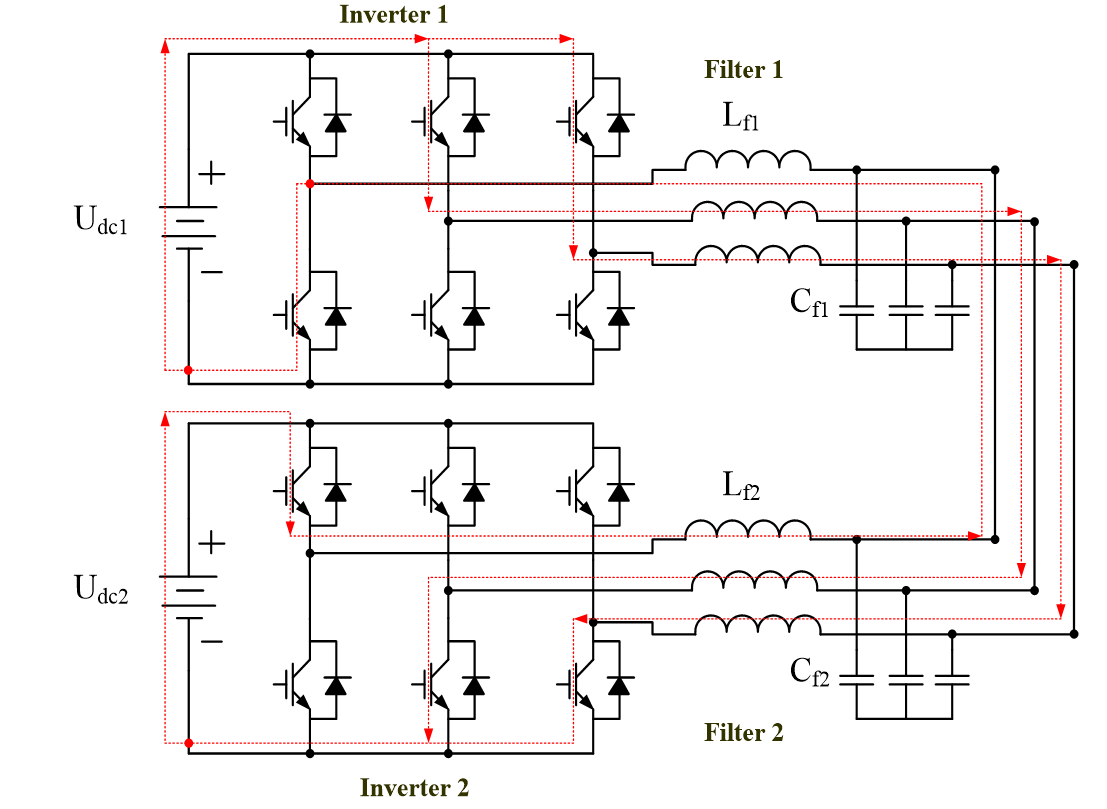
Illustration of the balanced current flowing between two inverters
In recent years, some researchers have proposed power sharing control techniques by compensating for line voltage drop 6, 7, 8. The purpose of the method is to eliminate impedance deviations of the lines. Power sharing between inverters becomes better. However, this method needs to know the line impedance parameter in advance, which is usually not available.
Besides, some researchers have proposed improved droop power sharing technique using communication. However, the use of communication will reduce the reliability of control, but this proposed method still has no measures to improve the reliability of the controller 9.
In addition, there are also some studies using master/slave control method, this method does not need to know the line impedance parameters in advance. However, this method requires a central controller and high bandwidth communication, which affects the cost of the controller. Even more important is the need to consider the reliability of the controller in the event of a communication bus interruption.
In this paper, a method to improve the traditional droop controller is proposed based on the idea of voltage drop compensation, the purpose of the proposed method is to eliminate the deviation of impedance parameters. Besides, the paper also presents the method to improve the reliability of the proposed controller. As a result, the proposed controller has the following contributions:
• The proposed controller gives accurate power sharing results.
• The controller is easy to use, no need to know the line parameters in advance.
• The controller can divide power well in case the communication bus is interrupted.
Proposed control method
Typically, an independent microgrid has the structure shown in Figure 3. The inverters are connected to a common bus at the point of common coupling (PCC) through the lines. Renewable energy sources, small generators, etc. are concentrated on the DC bus of the inverters. Microgrids typically include local loads and public loads.

Equivalent diagram of inverters connected in parallel in an independent microgrid
Each inverter is considered a power source, the output power of each inverter will supply local loads in that area. The remaining power of the inverter will be transmitted on the line to the common PCC bus to supply public loads or connect to the grid. Because the impedance of the lines can be different and the inverters can also be different. Therefore, control is needed to divide the power between the inverters. The proposed controller needs to use an energy management system (EMS) to regulate the voltage at the output of the inverters, the controller only needs to use low bandwidth communication.
Theoretical basis of the proposed control method
According to research 1, 2, 3, 4, 5, 6, 7, 8, 9, 10, 11, 12, the power running on the line is calculated according to the expression :
From formula (1), we have the expression to calculate real power and reactive power running on the line:
In there:
R(Ω) and X(Ω) are impedance parameters of the line.
V(voltage) is the voltage at the beginning of the line.
P(W) and Q(Var) are the powers running on the line.
V(voltage) is the voltage at the PCC.
δ is the phase difference angle of the voltage V anh V: δ = δ - δ
= R + jX
Substitute the following expressions into (2) and (3):
Combining equations (2) and (3), we have:
Combining equations (4) and (5), we have:
The actual angle between the output voltage of inverters and PCC bus voltage d is a small value, so sind≈d and cosd=1, X>>R, from equation (6 ) and (7) we have:
Equations (8) and (9) show that: P depends on frequency f, Q depends on voltage V. From there, we can establish P/f and Q/V droop controller to control the power of the inverters as follows:
Where:
V is the nominal amplitude voltage.
ω is the nominal frequency.
V is the measured amplitude voltage of the inverter
ω is the measured frequency of the inverter
P is the nominal active power of the inverter.
Q is the nominal reactive power of the inverter.
m and m are the droop coefficients, which are calculated as follows:
From the above equations, it is shown that a very small change in line impedance will have a large effect on the transmit power of the inverters. Analysis and simulation results in the study 11, 12, 13, 14, 15, 16, 17, 18, 19, 20 show that the impedance of the cable line or the impedance of the overhead line has little effect on the transmit power of a separate inverter, but it has a great impact on many parallel connected inverters in the Microgrid. In practice, the Microgrid consists of inverters connected in parallel, which are connected to the load via a long line, and it is clear that the line impedance significantly affects the control quality of the system and can lead to system instability, a drop in voltage by the impedances causes a bias in the output power control of the inverters.
When the microgrid is in a stable state, the inverters in the microgrid will operate at the same frequency, so the power P of the inverters is almost not affected by the line impedance parameter. However, the power Q of the inverters depends on the voltage drop of the line, so the power Q is significantly affected by the line impedance parameter.
The presence of local loads stuck at the output of inverters is also the cause of deviations in reactive power sharing between inverters in an islanded microgrid.
Deviations in line impedance parameters cause deviations in reactive power division. This problem can be explained by the following equation and figure:
Combining expressions (11) and (13) we get Figure 4.
Consider two inverters with the same rated capacity, connected to the PCC point through two lines with different impedances.
Because the two inverters are the same, the Q/V droop controllers for these two inverters are also the same, they are determined according to (11) and (12). The curve droop Q/V (11) and (12) are also shown in Figure 4.

The curve shows the change of reactive power according to line impedance
Figure 4 shows that, assuming there are two inverters with the same rated power so the droop Q/V characteristic curve is the same, they are connected to the PCC point by two different lines so the voltage characteristic curve of The two inverters are also different. As a result, the power Q generated at the output of the two inverters is also different.
The proposed controller
The graph of droop Q/V in (11) has a slope that depends on (12). When the slope (12) changes, the shared reactive power will change.
Therefore, in this paper, a control method is proposed to change the slope of the droop Q/V characteristic curve to reduce the error in dividing reactive power between inverters.
For the conventional Droop controller, the slope m is fixed according to (12), and the slope m in the proposed controller is adjustable.
The proposed controller has a diagram in Figure 5.

Schematic diagram of the proposed controller
The proposed controller includes the following blocks:
• Power calculation block and low pass filter: This block measures the voltage at the output of the inverter and the current on the line, then calculates the power and low-pass filters, the output of this block is the power P and Q.
• The proposed droop control block is implemented according to equations (10), (16) and (17). This block is presented in detail in section (b). The output of this block will generate a reference voltage for the voltage at the output of the inverter.
• Voltage and current controller to control the voltage and current at the inverter output according to the reference value.
Power calculation and low pass filtering
The instantaneous power p and q are calculated according to the instantaneous value of the current flowing on the line (i) and the voltage at the beginning of the line (v) in a stationary dq0 frame:
The proposed controller
In this paper, the proposed controller is presented in detail in Figure 6, this is an improvement from the traditional Droop controller. For the traditional Droop controller, the slope m is fixed, while the slope m in the proposed controller is adjustable. The slope m is adjusted for load changes through the energy management system (EMS). This is shown in formulas (16) and (17).
At the same time, to improve the reliability of the proposed controller in case the communication link is lost, the proposed controller is equipped with additional logic gates as shown in Figure 6.
The power P of the inverters is almost not affected by the line impedance parameter. However, the power Q of the inverters is significantly affected by the line impedance parameter. Therefore, sharing power P to the inverters is still done according to expression (10). However, the Droop Q/V equation (11) for reactive power sharing is improved as follows:
The equation (16) shows that the slope m in (11) is adjusted by an amount ∆m.
Where:
The ∆m in equation (16) is corrected by adjusting the Q value through the energy management system (EMS).
The EMS collects information about the reactive power Q of each incoming inverter.
On the other hand, the EMS also relies on the load power consumption to calculate the reference Q power value for each inverter. After that, the EMS will send the reference power value Qback to each inverter, this reference power Q is fed into the controller in equation (17) to adjust the slope of the Q/V droop curve. This helps divide power between inverters more accurately.
Depending on the technical specifications of the communication network, we choose the speed of information collection from the inverters sent to EMS or the reference power calculation results from EMS sent back to the inverter.
The reference reactive power value Qi* is also adjusted to vary according to the load. Therefore, each inverter also adjusts its reference value according to changes in load. This means that the slope adjustment of the droop Q/V characteristic curve is also changed according to the load. So the accuracy of power sharing is better.
In case of communication disconnection, the controller still operates with the last adjusted value, due to the use of the integration step in expression (17) and the logic gates in Figure 6, this process is still maintained until communication is reconnected. Therefore, if during the time the communication connection is lost but the load does not change, the power sharing is still guaranteed to be accurate. In case the load changes while communication is disconnected, the sharing error is still acceptable, the power sharing result is still better than the traditional droop controller.
The receiver has the ability to detect communication timeouts. In case of communication loss, the logic gate block will disable the control loop and the reference voltage at the controller output is kept constant. change until communication is restored. In case of communication delay, EMS detects communication timeout from inverters, it will block further data updates to all inverters until communication is restored.
The proposed controller for exact power sharing and improved reliability is shown in Figure 6, it consists of formulas (10), (16), (17), and logic gates.
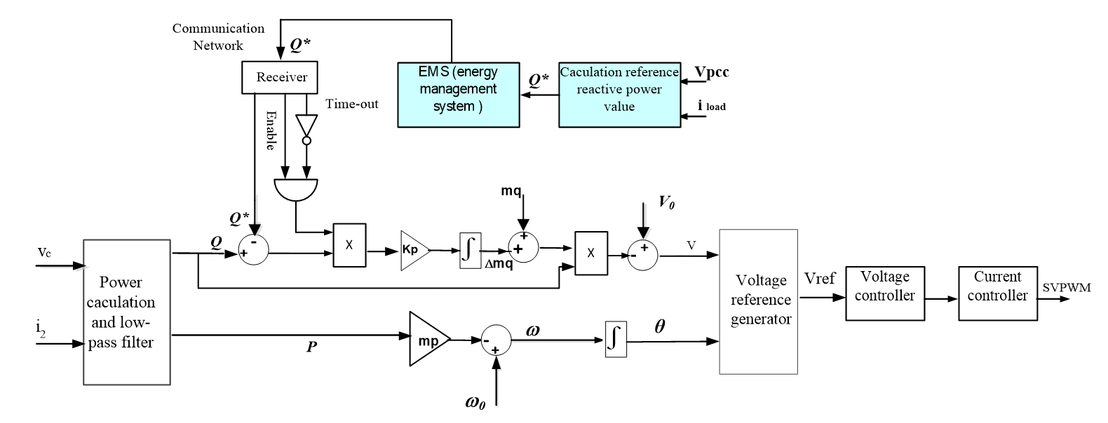
Block diagram of proposed Droop control for an inverter
Design a current and voltage controller
Based on the equivalent circuit shown in Figure 7, we set up these controllers.
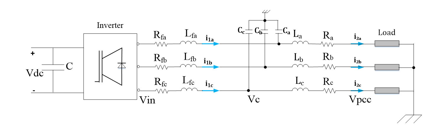
Equivalent schematic of inverters connected to a load.
Where:
R (Ω) And L (H) are resistor and inductance of the line
R (Ω) and L (H) are resistor and inductance of the filter (H).
Applying Kirchhoff's laws to the circuit of Figure 7, we have the following equations:
Equations (18) and (19) can be written as:
Based on expressions (20) and (21) we can set up the voltage controller:
Where:
Equations (24) to (27) are for the voltage controller.
Based on expressions (22) and (23) we can set up the current controller:
Where:
Equations (28) to (31) are for the current controller.
Simulation Results and Discussion
Simulate power control for a microgrid consisting of three inverters connected in parallel using Matlab/simulink software. Simulations are performed by the conventional controller and the proposed controller to compare the results. Simulation parameters are given in Table 1.
Simulation Parameters
|
Parameters |
Values |
Parameters |
Values |
|
DC link voltage Vcd (V) |
600 |
Nominal frequency f0 (Hz) |
50 |
|
Filter Lf (mH) |
4.2 |
Nominal power (kVA) |
4 |
|
Filter Rf (Ω) |
0.1 |
Nominal voltage VAC,p (V) |
310 |
|
Filter C (µF) |
2.2 |
mq (V/Var) |
1.05e-4 |
|
fz(kHz) |
10 |
mp (rad/s /W) |
1e-4 |
|
kpv |
0.1 |
kpi |
10 |
|
Kiv |
0.05 |
kii |
1 |
|
Line impedances | |||
|
L1(mH) |
1 |
R1(Ω) |
1.2 |
|
L2(mH) |
0.8 |
R2(Ω) |
0.9 |
|
L3(mH) |
0.5 |
R3(Ω) |
0.7 |
Case 1:
Perform power sharing simulation for three inverters in an independent microgrid. To show the effectiveness of the proposed controller, we perform simulations using two controllers (traditional Droop controller and proposed Droop controller) and compare their results.
Rated power ratio 1:1:1
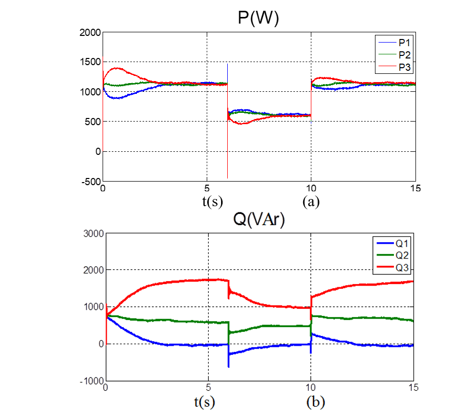
Simulation of power sharing using traditional Ddrop control (a) the active power sharing among three inverters; (b) the reactive power sharing among three inverters
Figure 8a shows that the active power sharing has negligible error, because the active power is not affected by the line impedance, the active power sharing result is exactly according to the ratio of rated power 1:1:1 of them. Figure 8b shows that the reactive power sharing has a very large error, because the reactive power is affected by the very large line impedance, the result of reactive power sharing is not correct according to the ratio of rated power. of them. Therefore, the traditional drop controller needs to be improved in the case of different transmission line impedances.
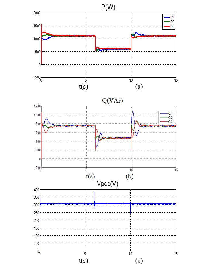
Simulate power sharing using proposed Droop control(a) the active power sharing among three inverters; (b) the reactive power sharing among three inverters; (c) Voltage at the PCC.
Figure 9a and 9b show that the active and reactive power of the three inverters are exactly in the ratio 1:1:1, although there are differences in line impedances and local loads. The deviation in power sharing is negligible and ensures voltage quality in the microgrid (V = 307.5V).
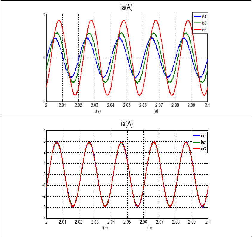
Current on line a of three inverters, (a) Using traditional Droop controller, (b) Using proposed controller
Figure 10a shows when we performed with a conventional Droop controller, the current on phase a of the inverters was out of phase and their amplitude was not equal. Figure 10b shows when we performed with the proposed controller, the current on phase a of the inverters is overlapped together and their amplitude was equal. Because the proposed controller adjusts the slope of the droop Q/V characteristic curve, the deviation of line impedances and local loads is eliminated.
Rated power ratio 2:1:
This case performs power-sharing for 2 inverters with a ratio of 2:1 using the proposed controller. Simulation results: power-sharing and voltage at the PCC are presented in Figure 11.
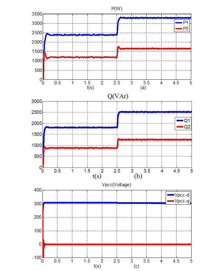
Simulate power sharing usingproposed Droop control(a) the active power sharing among two inverters; (b) thereactive power sharing among two inverters; (c) Voltage at the PCC.
Figure 11a and 11b show that the power of the two inverters is divided exactly according to the rated power ratio of 2:1, even though the line impedance is different and the load changes. At time t=2.5s the load changes but the reactive power is still divided in the correct 2:1 ratio and there is a negligible deviation. The quality of voltage supplied to the load is within allowable limits.
Case 2:
Simulate power sharing for three inverters connected in parallel in the microgrid using the proposed controller, the rated power of the two inverters is in the ratio 1:1:1. Suppose communication is lost at 3s and restored at 8s, the load changes during this period. Simulation results are shown in Figure 12.

Simulate power sharing using proposed Droop control in case the communication is lost (a) the active power sharing among three inverters; (b) the reactive power sharing among three inverters
Simulate power sharing for 3 inverters with rated power in the ratio 1:1:1 using the proposed controller in case of communication loss.
In 0-3 seconds, the communication bus is connected; within 3-8 seconds, the communication bus is disconnected; After 8 seconds communication is reconnected; The load capacity drops at 5s.
Figure 10a shows that, within a period of 0-3 seconds, the communication is connected and the proposed controller has performed a correct reactive power sharing in the ratio 1:1:1.
The communication bus is interrupted for a period of 3 seconds to 8 seconds. However, during the period from 3s to 5s, the load does not change so the accuracy in power sharing is still maintained. At 5s, the load starts to change and communication fails, so the power sharing result in the time period from 5-8s has errors, although the power sharing has deviations during this time period, the error is share is still lower than the results in Figure 8b.
At 8 seconds, communications are reconnected, and power sharing is now correct. Figure 12b shows that the current in phase a of the lines before and after the communication bus stops working is still well maintained.
CONCLUSION
This paper has proposed an improved power control method, which overcomes the disadvantages of the traditional method. The simulation results show that the proposed method gives accurate power sharing results in situations that often occur in practice, and the quality of voltage supplied to the load is satisfactory. The proposed controller is easy to implement, does not need to know exact line impedance parameters, is highly reliable, and is suitable for practical conditions.
CONFLICT OF INTEREST
There is no conflict of interest regarding this manuscript.
AUTHORS’ CONTRIBUTION
Xuan Hoa Thi Pham have writen this entire paper.