


A Modified 2-Dimensional Decentralized Interleaving Algorithm for Multilevel Multileg Converters
- Faculty of Electrical and Electronics Engineering, Ho Chi Minh City University of Technology (HCMUT), Ho Chi Minh City, Vietnam
- Vietnam National University Ho Chi Minh City (VNU-HCM), Ho Chi Minh City, Vietnam
- Power Electronics Group, LAPLACE, Université de Toulouse, CNRS, INPT, UPS, France, 2, rue Charles Camichel - BP 7122 - 31071 Toulouse cedex 7
Abstract
This paper proposes a modified algorithm to interleave the carrier signals in decentralized controller for multi-level multi-leg converter. Structure of these converters includes a number of semiconductor modules which are arranged in series and parallel to compose a matrix. The serial modules allow increasing the voltage levels of converter, while, the parallel modules allow increasing the working power of converter, therefore, the multi-level multi-leg converter can be applied in high-voltage high-power systems. The size of matrix can be changed by adding or removing the rows or columns at required positions while the system is working. The multi-level multi-leg converter can be controlled by a traditional algorithm which includes a central micro-controller using for all modules. However, this algorithm has a disadvantage when the system has a large amount of modules, at that time, the controller does not have enough resource to operate the algorithm. A decentralized algorithm has proposed to solve this problem, in this method, each module has its own controller to communicate and exchange the information with the horizontal and vertical neighboring modules over the communication channel. From the collected information, the controller of each module will calculate the phase angle of that module so that all carrier signals are interleaved successfully. This proposed algorithm also has a disadvantage, it cannot work correctly with matrices where number of rows and columns have non-one common divisor, they are called special matrices. This research focus on adjusting the algorithm so that it can work with all type of matrices including the special matrices. The ability of dynamical restructuring of system as well as the convergence speed of the algorithm are also considered and evaluated when some modules are added or removed. The research demonstrated the efficiency and the feasible by simulation results and experiment results. The proposed algorithm is simulated by the MATLAB/SIMULINK program and is experimented on micro-controller TMS320F28069.
Introduction
In the recent years, multi-level multi-leg converters have been strongly researched and developed, and they are now used in numerous applications. These converters are constructed from several switching-cells connected in series and parallel 1, 2, 3.
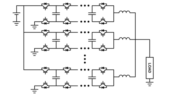
Each switching cell is created from semiconductor switches and capacitors that have medium current and voltage ratings. The serial connection allows converters to operate at high DC-bus voltage by assembling multiple switching cells together4, 5, 6, 7, 8. A leg of the converter is formed by a series of switching cells and an inductor. The parallel connection allows converters to operate at high load current by assembling multiple legs together9, 10, 11, 12. For example, Figure 1 shows a flying capacitor multi-level multi-leg converters.
Multi-level multi-leg converter have many components that need to be controlled. As a result, the central microcontroller must have capability to communicate with all cells. This leads to complexity in the control system, which may make it difficult to implement in large-scaled projects.
To overcome the disadvantages of a central microcontroller, a decentralized control algorithm has been proposed in previous studies13, 14, 15. In this method, each cell has its own controller and exchanges necessary information with the nearest neighboring cells to implement the algorithm. In case of a multi-level multi-leg converter, this approach can also be used to establish communications between the cells in a one-dimensional serial chain in order to interleave the PWM signals. This process may require a relatively high computation time to reach the steady-state for the case of a multi-level multi-leg converter because this type of converter contains a large number of cells and this algorithm is implemented from the beginning to the end of the chain. The configuration of this algorithm is shown in Figure 2.

Flying capacitor multi-level multi-leg converter

Basic decentralized interleaving algorithm of multi-level multi-leg converter
To increase the rate of convergence, the 2-dimensional (2D) decentralized control algorithm has been introduced. In this method, each cell exchanges information with the nearest neighboring cells in horizontal or vertical axis, depending on its position16. The only information exchanged is the phase of the triangular wave and the decentralized micro-controllers adjust their own phase based on this information. However, it cannot work with some configurations which have special number of rows and columns, which is the disadvantage of the conventional 2D algorithm.
In this paper, the 2-dimensional decentralized control algorithm has been improved to operate with all configurations of multi-level multi-leg converter. Simulation and experiment are also implemented to demonstrate the superiority of algorithm.
Proposed 2D decentralized interleaving method
The previous studies have presented the equation for one-dimension phase shift, as shown in (1) and (2)
In multi-level multi-leg converters, cells are arranged in rows and columns, and horizontal and vertical interleaving in those rows and columns are performed sequentially.
First, the neighboring cells of the first column exchange information with each other to achieve the vertical interleaving. After that, all other cells in all rows perform horizontal interleaving simultaneously (Figure 3). If the control systems operate correctly, the cells will reach the expected interleaved state after a certain duration. Because of their important role, the first column and the first row cannot be removed during the process of operation.
At the beginning of the algorithm, the phase of the first cell remains constant at 0° throughout the implementation, while other phases are set to 180° and can be changed to reach an equilibrium point. However, this algorithm does not work for matrices where the number of rows and columns have a non-one common divisor, these matrices are called special matrices.

The basic 2D cell linking
Some cases of matrices are shown in Tables 1, 2 and 3. As shown, the 3x3 and 4x4 matrices fail to properly interleave the carrier of cells.
To overcome the divergence of basic 2-dimensional interleaving algorithm for special matrices, the cell linking must be adjusted. Specifically, the first cell of the last row exchanges information with the second cell of the first row. The system configuration is shown in Figure 4.
With this adjustment, vertical and horizontal interleaving can be performed simultaneously and the problem of special matrices can be solved as shown in Tables 4 and 5.

The proposed 2D cell linking
Carrier’s phase of in basic algorithm
|
0° Cell 11 |
120° Cell 12 |
240° Cell 13 |
|
120° Cell 21 |
240° Cell 22 |
0° Cell 23 |
|
240° Cell 31 |
0° Cell 32 |
120° Cell 33 |
Carrier’s phase of 3x4 converter in basic algorithm
|
0° Cell 11 |
90° Cell 12 |
180° Cell 13 |
270° Cell 14 |
|
120° Cell 21 |
210° Cell 22 |
300° Cell 23 |
30° Cell 24 |
|
240° Cell 31 |
330° Cell 32 |
60° Cell 33 |
150° Cell 34 |
Carrier’s phase of 4x4 converter in basic algorithm
|
0° Cell 11 |
90° Cell 12 |
180° Cell 13 |
270° Cell 14 |
|
90° Cell 21 |
180° Cell 22 |
270° Cell 23 |
0° Cell 24 |
|
180° Cell 31 |
270° Cell 32 |
0° Cell 33 |
90° Cell 34 |
|
270° Cell 41 |
0° Cell 42 |
90° Cell 43 |
180° Cell 44 |
Simulation results
The simulation model is implemented using MATLAB/ SIMULINK software for a 4-level 4-phase converter. The inputs and outputs of a cell are shown in Figure 5 and its parameters are explained in Table 6. These cells are connected through IN and OUT channels for receiving and transmitting the phase angles.
All the cells are divided into three types: the master cell (type 0), the first cell of row (type 1) and normal cell (type 2). Each type has its own method of communication and calculation. Besides, a cell can be enabled or disabled by changing its EN signal. The flowchart of the algorithm is shown in Figure 6.
In this section, three separated case studies were simulated, including two special matrices (3x3 and 4x4) and one normal matrix (3x4). The gate signals of the whole system operate at 10 kHz.
Carrier’s phase of 3x3 converter in proposed algorithm
|
0° Cell 11 |
120° Cell 12 |
240° Cell 13 |
|
40° Cell 21 |
160° Cell 22 |
280° Cell 23 |
|
80° Cell 31 |
200° Cell 32 |
320° Cell 33 |
Carrier’s phase of 4x4 converter in proposed algorithm
|
0° Cell 11 |
90° Cell 12 |
180° Cell 13 |
270° Cell 14 |
|
22,5° Cell 21 |
112,5° Cell 22 |
202,5° Cell 23 |
292,5° Cell 24 |
|
45° Cell 31 |
135° Cell 32 |
225° Cell 33 |
315° Cell 34 |
|
67,5° Cell 41 |
157,5° Cell 42 |
247,5° Cell 43 |
337,5° Cell 44 |
In addition, the dynamic response of the proposed algorithm was also demonstrated through a system reconfiguration simulation. The system was simulated in 25 ms, with a 4×4 at the beginning. The fourth row was then removed at 5 ms, and the fourth column was removed at 10 ms. After that, these rows and columns were reinserted to restore the original state, with the fourth column reinserted at 15 ms and the fourth row at 20 ms. After each reconfiguration, the system quickly reached the new steady state. The process of reconfiguration is shown in Figure 7 and the simulation results are shown in Figure 8 to Figure 10 respectively.
As shown in Figure 11, the proposed algorithm worked perfectly with the two types of matrices, all the carrier’s phase of all cells reached a steady value after a short duration.

Model of a cell
Parameters of experimental model
|
IN_L |
Carrier’s phase from the left cell |
|
OUT_L |
Carrier’s phase to the left cell |
|
IN_R |
Carrier’s phase from the right cell |
|
OUT_R |
Carrier’s phase to the right cell |
|
IN_T |
Carrier’s phase from the top cell |
|
OUT_T |
Carrier’s phase to the top cell |
|
IN_B |
Carrier’s phase from the bottom cell |
|
OUT_B |
Carrier’s phase to the bottom cell |
|
EN |
Enabled signal of cell |
|
TYPE |
Type of cell |
|
α |
Carrier’s phase of this cell |

The flowchart of proposed algorithm

The process of reconfiguration

Simulation result of 3x3 system

Simulation results of 3x4 system

Simulation results of 4x4 system

Simulation results of reconfiguration
Experimental results
In this section, some experimental results will be presented. The experimental model contains 16 cells which are arranged in 4×4 matrix. Every cells are controlled by their own micro-controller TMS320F28069 which are loaded the same programme. The switching frequency is fixed at 10 kHz.
Communication channels are set-up to exchange information between the cells. Each micro-controller has two types of communication, so it is suitable for the systems with many rows and columns. Serial peripheral interface (SPI) and serial communication interface (SCI) are used for horizontal communication and vertical communication respectively. The baud rate of all communication channels is fixed at 5 Mbps.
Because the amount of bits is limited for each transfer, a data must spend many stages to be communicated and synthesized completely. These stages must be synchronized in order that the algorithm operates accurately. The first micro-controller has the role of the master, which generates the synchronization signal for all other controllers. Frequency of the synchronization signal is 50 kHz, this value guarantees that everything can be done completely in a switching cycle.
The experimental model was made in the laboratory and is shown in Figure 12. Some of the experimental case studies are similar to those described in the previous section. The carrier signal's phase of each cell is observed through a LCD display, as shown in Table 7 to 9. The gate signal of the cells are shown in Figure 13 to Figure 15.
Conclusion and discussion
In this paper, a modified 2-dimensional interleaving algorithm for multi-level multi-leg converters is presented. The proposed algorithm can efficiently handle special and normal matrix cases, and it demonstrates fast convergence to a steady state even when the system undergoes dynamic reconfiguration. Our simulations and experimental results showed that the proposed algorithm outperforms existing approaches in terms of simplicity. Furthermore, the proposed algorithm is scalable and can be extended to support converters with a higher number of levels and phases.
The experimental results confirmed the effectiveness of our approach in a practical setting. The experimental setup demonstrated that the proposed algorithm can be implemented using commercially available micro-controllers and can achieve stable operation with high accuracy.
Overall, the proposed algorithm has significant potential for applications in power electronics and can contribute to the development of more efficient and reliable multi-level multi-leg converters.

4-level 4-phase converter with decentralized controllers
Carrier’s phase of model 3x3 converter
|
000,00 Cell 11 |
120,00 Cell 12 |
240,00 Cell 13 |
|
040,00 Cell 21 |
160,00 Cell 22 |
280,00 Cell 23 |
|
080,00 Cell 31 |
200,00 Cell 32 |
320,00 Cell 33 |
Carrier’s phase of model 3x4 converter
|
000,00 Cell 11 |
090,00 Cell 12 |
180,00 Cell 13 |
270,00 Cell 14 |
|
030,00 Cell 21 |
120,00 Cell 22 |
210,00 Cell 23 |
300,00 Cell 24 |
|
060,00 Cell 31 |
150,00 Cell 32 |
240,00 Cell 33 |
330,00 Cell 34 |
Carrier’s phase of model 4x4 converter
|
000,00 Cell 11 |
090,00 Cell 12 |
180,00 Cell 13 |
270,00 Cell 14 |
|
022,50 Cell 21 |
112,50 Cell 22 |
202,50 Cell 23 |
292,50 Cell 24 |
|
045,00 Cell 31 |
135,00 Cell 32 |
225,00 Cell 33 |
315,00 Cell 34 |
|
067,50 Cell 41 |
157,50 Cell 42 |
247,50 Cell 43 |
337,50 Cell 44 |

Gate signals of 3x3 system

Gate signals of 3x4 system

Gate signals of 4x4 system
ACKNOWLEDGMENTS
We acknowledge the support of time and facilities from Ho Chi Minh City University of Technology (HCMUT), VNU-HCM for this study.
CONFLICT OF INTEREST
The authors declare that they have no conflict of interest.
AUTHORS’ CONTRIBUTION
Bao Anh Nguyen was responsible for proposing the model, analyzing the structure, and constructing the simulation and experimental models.
Quoc Dung Phan contributed by proposing the ideas and methodology, creating the control algorithm, and participating in the writing, editing, and refinement of the article.
Guillaume Gateau was in charge of analyzing the simulation results and also participated in the writing, editing, and refinement of the paper.