


Investigate the effects of the dimensional factors on resistance force in magnetorheological brake with the waveform boundary of a rotary disk
- Ho Chi Minh City University of Technology, VNUHCM, Vietnam
Abstract
There are many studies on applying magneto-rheological fluid (MRF) to braking systems and shock absorbers. This paper investigates the resistance caused by the MRF to the curved surface of the brake components to improve the braking and damping forces. MRF is also called a smart fluid whose viscosity can be controlled. This study uses the proposed model of the magnetorheological brake (MRB) of Nam and Ahn with the waveform boundary of a rotary disk. In this study, the Taguchi method is applied to build virtual experiments and investigate the influence of dimensional parameters of the brake component, including the radius of arc (Rrac), MRF gap (g), and the thickness of the part (b) on its resistance force (F). The resistance force caused by a non-planar surface's resistance is expected to be significantly larger than that of a flat surface. Overall, the results show that the MRF gap g (mm) has the most significant influence, followed by the radius of the arc (Rarc) and, then, the thickness (b) of the components. Thus, based on these parameters' effects, there will be a practical direction to improve the design of devices using this kind of MRF special brake or clutch.
Introduction
There many studies related to improving braking momentum in MRF-based brakes in recent years 1, 2, 3, 4, 5, 6, 7, 8, 9, 10, 11, 12, 13, 14, 15, 16, 17, 18, 19, 20, 21, 22. In particular, several studies have directly examined the behavior of magnetic fields to cover a large area to increase the brake force.
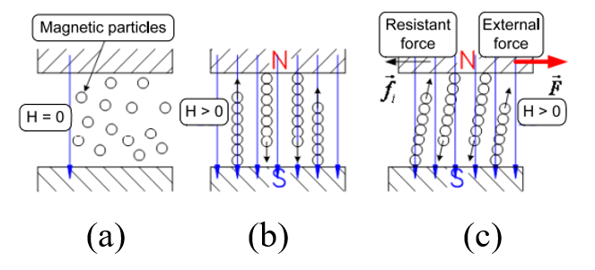
MRF behaviors in a change of magnetic field
(a)Without a magnetic field.
(b)With a magnetic field and without sliding.
(c) With magnetic field and sliding
Magnetorheological fluid (MRF) is an attractive, smart material widely used to develop devices in various industries, including automotive engineering, aerospace engineering, manufacturing, and medical fields. A typical MRF is a type of functional fluid that has a suspension of magnetic particles in inert carrier liquids. The particles, typically with a size in the order of 1–10 μm, are added to the fluid, such as mineral or silicone oils. MRF also contains small amounts of additives that affect the polarization of the particles or stabilization of the structure of the suspension to resist settling. The behavior of MRF is shown in Figure 1. When a field normally orients to the direction of the flow, the magnetic particles are arranged to form many parallel chains (fibrils) and placed across the flow. These fibrils are broken in some instances by the fluid flow, and the broken fibrils are reconnected to the next adjacent fibrils by the applied magnetic field, which is proportional to the shear stress τ. The fibrils cause the production of shear stress, which is largely independent of the strain rate. This is commonly referred to as the yield stress and is denoted as τ2. Through this shear stress, the resistant force is generated and controlled by the magnetic field. The is largely independent of the strain rate. This is commonly referred to as the yield stress and is denoted as τy2. Through this shear stress, the resistant force is generated and controlled by the magnetic field. The Bingham plastic model has the stress–strain rate relation of τ shown in equation (1) with the magnetic field B, dynamic viscosity η, and strain rate .
Some typical devices using MRF are Magnetorheological Brake (MRB), Magnetorheological Clutch (MRC), and Magnetorheological Damper (MRD). Furthermore, an MRF-based device possesses a distinctive advantage not found in conventional devices like servomotors and hydraulic machines, namely, the fail-safe function. This means that even in the event of failure during control action, MRF devices can continue to deliver passive device performance. This unique feature is made possible due to the presence of a carrier liquid in the MRF device, which serves a similar role as the viscous oil commonly employed in passive devices.
MRF-based brakes identified many different structural configurations to improve the effect of these smart fluids. Hung et al.15 made a notable enhancement by altering the coil layout design to augment both the coverage area and magnetic field strength in the active region of the fluid. In addition, some models increase the number of brake discs to increase the contact area of the liquid and the surface15. Nam et al.2 proposed an MRB incorporating a brake disk with a wave-shaped boundary (Figure 2), which provides braking torque produced by the effects of the material deformation process. The results illustrate that the output torque with this kind of structure is close to 600% larger than that of conventional brakes of the same size. Similar to Nam, C. Sarkar et al.7 used a parabolic-shaped rotating disc. In another study, A. Singh et al. 17 focused on a wedge-shaped MRC.
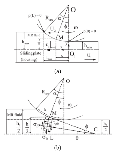
Nam
a) The resistance force caused by the sliding process.
b) The resistance force caused by the deforming process.
This paper proposes a simple equivalent model to investigate in detail the interaction between the conventional structure and the curve form. The simulation only estimates the values of the magnetic field to calculate the output resistance force. It is used to evaluate the influencing factors that affect the output force. In this case, since this is a simulation case only, the liquid covered will be neglected. An ANOVA statistic was performed to quantify the influence of the three input parameters, which are the MRF gap (g), radius (Rarc) of the arc, and thickness (b) of the components.
Materials and Methods
In this paper, the Taguchi method is used to set up the virtual experiment; The virtual model shown in Figure 3 is a simple element of the waveform boundary of a rotary disk, which is proposed in Nam et al. (2009)1. This model includes the gap-filled MRF (also called MRF gap) between sliding and fixed parts. The magnetic field will be applied to the MRF gap and varied by the coil through the magnetic core. In the proposed virtual experiment, three operating factors include the radius of the arc (Rarc), the fluid gap (g) between, and the thickness (b) of the observing object. The factors and their levels have been chosen according to a literature review of previous publications on the radius of the curve and the MRF1. For the design of experiments with three factors and three levels for each factor, a standard L27 orthogonal array was applied. To avoid systematic bias, the sequence in which these runs were carried out was randomized. The statistical analysis of the results was carried out using DoE in Minitab.
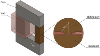
Concept of the virtual experiments
In this research, the Taguchi method is applied to examine which parameters affect the resultant resistance force caused by magneto-rheological fluid on the curve of the sliding part. The benefit of this method is that a minimal number of experiments are needed to study the effect factors on a pair of parameters. The levels of selected factors are shown in Table 1.
Selected Factors and Levels
|
Factor |
Unit |
Level | ||
|
1 |
2 |
3 | ||
|
Radius of arc (Rarc) |
mm |
4 |
5.5 |
7 |
|
MRF gap (g) |
mm |
0.2 |
0.5 |
0.8 |
|
Width of part (b) |
mm |
10 |
15 |
20 |
Steel 1008 is used for the core in this simulation model, and the MRF-132DG of Lord Corp. is applied for the MRF. The purpose of these samples is to facilitate the easy setting and measurement of output force. However, it is not changing the meaning of this study. When the applied magnetic field is caused by the coil, which has an NI of around 200-ampere turns, the behavior and value of the magnetic field (H) response in each sample are different. The magnetic field (H) value is averaged in the range L of the effective angle α ≤ 15 in the deforming process and sliding1. Figure 4 shows the effective zone (L) of the magnetic field defined by the angle of α in the MRF gap.
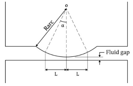
The effective zone (L) of the magnetic field is defined by the angle of in the MRF gap.
When applying a magnetic field, the general force per unit width of the arc is the sum of resistance forces in both models shown in equation (2). Where F is a resistance force; F is force caused by deformation theory F is force generated from the sliding process; and B is the thickness of the sliding part. In addition, the effect of mechanical friction, such as seal friction, bearing friction, and so forth, is neglected.
Results
The simulation results with the resistance force value (N) of the corresponding numbered test after calculation are described in Table 2 and Figure 5. In Table 2, the test samples No. 21, 20, 12, and 24 have obtained generated force by MRF which is higher than the others and have input parameters in bold rows.
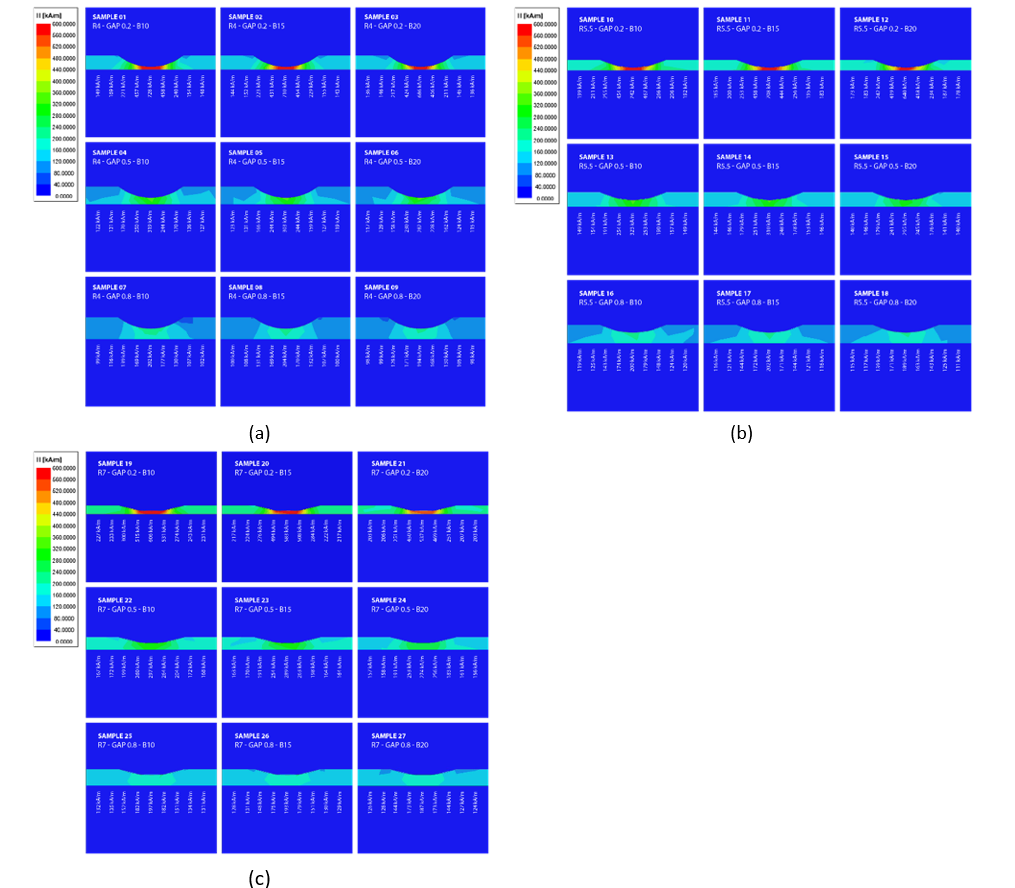
Response of magnetic field in a) Sample 1 - 9. b) Sample 10 – 18. c) Sample 19 – 27.
Simulation results
|
Sample No. |
Radius of arc, Rarc (mm) |
MRF gap, g (mm) |
Thickness, b (mm) |
Resistance Force, F (N) |
|
1 |
4.00 |
0.20 |
10.00 |
7.58 |
|
2 |
4.00 |
0.20 |
15.00 |
11.38 |
|
3 |
4.00 |
0.20 |
20.00 |
15.17 |
|
4 |
4.00 |
0.50 |
10.00 |
4.71 |
|
5 |
4.00 |
0.50 |
15.00 |
7.03 |
|
6 |
4.00 |
0.50 |
20.00 |
9.31 |
|
7 |
4.00 |
0.80 |
10.00 |
3.31 |
|
8 |
4.00 |
0.80 |
15.00 |
4.90 |
|
9 |
4.00 |
0.80 |
20.00 |
6.51 |
|
10 |
5.50 |
0.20 |
10.00 |
11.94 |
|
11 |
5.50 |
0.20 |
15.00 |
17.91 |
|
12 |
5.50 |
0.20 |
20.00 |
23.88 |
|
13 |
5.50 |
0.50 |
10.00 |
7.67 |
|
14 |
5.50 |
0.50 |
15.00 |
11.47 |
|
15 |
5.50 |
0.50 |
20.00 |
15.23 |
|
16 |
5.50 |
0.80 |
10.00 |
5.36 |
|
17 |
5.50 |
0.80 |
15.00 |
7.97 |
|
18 |
5.50 |
0.80 |
20.00 |
10.46 |
|
19 |
7.00 |
0.20 |
10.00 |
16.62 |
|
20 |
7.00 |
0.20 |
15.00 |
24.94 |
|
21 |
7.00 |
0.20 |
20.00 |
33.25 |
|
22 |
7.00 |
0.50 |
10.00 |
11.04 |
|
23 |
7.00 |
0.50 |
15.00 |
16.48 |
|
24 |
7.00 |
0.50 |
20.00 |
21.86 |
|
25 |
7.00 |
0.80 |
10.00 |
7.80 |
|
26 |
7.00 |
0.80 |
15.00 |
11.57 |
|
27 |
7.00 |
0.80 |
20.00 |
15.27 |
Discussion
To understand the influence of each factor with different levels on the resistance force (N), the average S/N ratios in each group were calculated and listed in Table 3. The average S/N ratios in Table 3 are plotted in Figure 6. The range of each factor (delta) is defined as the difference between the highest and the lowest average S/N ratios; the more extensive the range, the more significant influence of the corresponding factor on the surface quality.
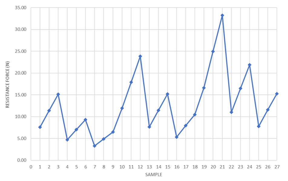
Resistance force (N) values of 27 samples
For more details, the results of the ANOVA with resistance force are presented in Table 4. The results of this analysis are performed at a significance level of α = 0.05, i.e., with a confidence level of 95%. Test samples No. 21, 20, 12, and 24 show that the study’s potential is apparent with the values of 33.25, 24.94, 23.88, and 21.86 N of force, respectively. Using the simple load-cell test bench can help in experimental testing, which is not the focus here.
In this study, MRF gap g is the most influential factor (34.78%), and the change in output force occurs very strongly in the range from 0.2 to 0.8 mm. The radius of the arc is the second most influential factor, with a 33.40% influence on output force. Thickness has the smallest range and has the most minor impact, 1.38%, on the generated resistance force.
By following the criteria of a more significant resistance force with a larger S/N ratio, Figure 7 with marked red circles can be used to determine the optimal factors to achieve the maximum force. The combination to achieve the most significant output force is a radius of 7.0 mm (level 3), a fluid gap of 0.2 mm (level 1), and a thickness of 10 mm (level 1). This will be a significant key for designing the new MRB using the waveform boundary of the rotary disk.
Response Table for Signal-to-Noise Ratios
|
Level |
Radius of arc, Rarc |
MRF gap, g |
Thickness, b |
|
1 |
16.27 |
23.67 |
20.13 |
|
2 |
20.4 |
19.8 |
20.07 |
|
3 |
23.49 |
16.7 |
19.96 |
|
Delta |
7.22 |
6.96 |
0.17 |
|
Rank |
1 |
2 |
3 |
Analysis of variance (ANOVA) for Resistance Force
|
Source |
DF |
Adj SS |
Adj SS (%) |
Adj MS |
F-Value |
P-Value |
|
Radius of arc |
2 |
439.64 |
33.40 |
219.822 |
10.98 |
0.001 |
|
MRF gap |
2 |
458.00 |
34.78 |
228.999 |
11.44 |
0.000 |
|
Thickness |
2 |
18.19 |
1.38 |
9.093 |
0.45 |
0.641 |
|
Error |
20 |
400.27 |
20.014 | |||
|
Total |
26 |
1316.10 |
The thickness parameter shows that it shows a distrust P-value larger than 0.05. The number of samples may be a big reason for this. In addition, expanding the range of the variable Rarc and Fluid gap is necessary for further conclusions. However, increasing the radius of the arc until the curve becomes linear will neglect the effect of deforming processes. On the other hand, the fluid gap is the most challenging part of manufacturing because the tolerance limitation must be well controlled for the number of 0.2 mm. Therefore, the range of these parameters should be discovered in further research for optimizing the output resistance force in MRF-based brake systems.
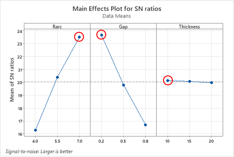
Influence of dimensional parameter according to the survey values on the resistance forceindex F.
Conclusions
The findings of this study hold the potential to make substantial contributions to the development and production of sliding components in MRB. The resistance force can be varied by fine-tuning the input current, thickness, and fluid properties, resulting in enhanced overall performance. With optimization efforts in parameters with maximum resistance force, the design has the potential to bring about increased energy efficiency across diverse industrial and engineering implementations.
By simulation using Minitab and Ansys Maxwell, the paper shows that MRF gap g is the most influential factor, the radius of the arc Rarc is the second most influential factor, and the thickness b has less impact on the generated resistance force in the structure of a brake disk with a wave-shaped boundary.
Based on these results, the optimal design of MRB using the wave-shaped boundary of a rotary disk will be focused on in the next studies. It will compare the outcomes of the simulation model with those of the physical model.
Abbreviations
MRF: Magneto-Rheological Fluid
MRB: Magneto-Rheological Brake
MRC: Magneto-Rheological Clutch
MRD: Magneto-Rheological Damper
Competing Interests
The authors wish to confirm that there are no known conflicts of interest associated with this publication, and there has been no significant financial support for this work that could have influenced its outcome.
Authors' Contributions
The first author (T. H. Nam) conceived of the study, the second author (D. N. H. Long) participated in its design and simulation, and helped to draft the manuscript. The authors read and approved the final manuscript.