


A passivity-based neural control using genetic algorithm for a DC-DC boost power converter
- Trường Đại học Bách khoa- ĐHQG TP. HCM
- Eastern International University, Vietnam
- Ho Chi Minh City University of Technology (HCMUT), Vietnam National University Ho Chi Minh City, Vietnam
Abstract
In this paper, a passivity – based neural control using genetic algorithm of a DC-DC boost power converter is proposed. The output of a DC-DC boost power converter is an inductor current. The control input is the duty ratio. Using a co-ordinate transformation of state variables and control input, a DC-DC boost power converter is passive. A new plant is zero-state observable and the equilibrium point at origin of this plant is asymptotically stable. A passivity - based control law is constructed by using neural network. The goal is that the capacitor voltage is equal to the desired voltage. The neural network has three layers: the input layer, the hidden layer and the output layer. The activation function of the hidden layer is tangent-hyperbolic and the activation of the output layer is linear. The weights of neural network are also adjusted optimally by genetic algorithm using decimal encoder. The general algorithm of neural network for a passivity-based control is also constructed. Simulation results are done with Simulink in MATLAB. Simulation results of the passivity-based neural control without using genetic algorithm are good and show that the capacitor voltage v is kept at the desired voltage Vd when the input voltage E and the load resistor R vary. Further, the simulation results of the passivity – based neural control using genetic algorithm have good performance such as short settling time, 3 ms and small steady-state error, which is indicated by IAE (integral absolute error (IAE) of the desired voltage and the capacitor voltage), 0.0343. The results of passivity-based neural control using genetic algorithm shows that the capacitor voltage is kept at the desired value Vd. Finally, simulation results show that the passivity-based neural control using genetic algorithm is better than the passivity-based neural control.
Keywords: dc-dc boost power converter, neural control, passivity – based control, genetic algorithm.
Introduction
The neural control and the passivity-based control have been investigated by many researchers. Ortega et al. 1 presented the passivity-based control of DC-DC boost converter and buck converter, the sliding mode control and the adaptive control for DC-DC power converter. W. He et al. 2 presented the passivity-based control of DC-DC boost power converter under time-varying disturbances via generalized proportional integral observer. Cisneros et al.3 presented the passivity-based control of the bilinear systems and its applications to the boost and modular multilevel converters. The sliding mode control and the passivity-based control were presented by Hoai Nghia Duong 4. Khalil 5 presented the Lyapunov stable theory, a passivation and the passivity-based control of a two-degree of freedom robot. M. H. Huynh, H. N. Duong and V. H. Nguyen6 presented the control system based on passivity-based control for a bicycle robot.
T. Hayakawa et al.7 described the passivity-based adaptive output feedback control using neural network for nonlinear nonnegative dynamical systems. W. Li et al.8 presented the passivity-based distributed tracking control problem of networked agents in the presence of uncertainty and external disturbance. M. Norgaard et al. 9 presented the multilayer perceptron network and applications to identification of nonlinear systems, the inverse control, and the internal model control of nonlinear systems. Duc Minh Nguyen et al.10 described the control of the inverted pendulum system using neural networks. D. Muthirayan and P. P. Khargonekar11 presented a neural adaptive control for a continuous-time system. G. Escobar et al. 12 presented an experimental comparison of several nonlinear controllers such as input-output linearization, sliding mode control, and passivity-based control for DC-DC boost power converter. M. A. Hassan et al.13 presented the passivity-based control combined with adaptive control of DC-DC buck converter with constant power loads in DC microgrid systems.
Further, genetic algorithm was described by M. Mitchell14. K. S. Tang et al. 15 presented an optimization of feedforward neural networks of which topology and weights were adjusted optimally by genetic algorithm. The neural networks integrated adaptive backstepping control of DC-DC boost converter were presented by T. K. Nizami and A. Chakravarty 16. J. Aguila-Leon et al. 17 presented an optimal PID parameters tuning for a DC-DC boost converter. M. Mohammedi et al. 18 described the fuzzy logic and passivity-based controller applied to electric vehicle using fuel cell and supercapacitors hybrid source. A passivity-based control using genetic algorithm was proposed by M. N. Huynh, H. N. Duong and V. H. Nguyen19. The advantage of the passivity-based control is the asymptotical stability of the equilibrium point at origin of the plant. The passivity-based control combined with sliding mode control for a DC-DC boost power converter was presented by Minh Ngoc Huynh, Hoai Nghia Duong and Vinh Hao Nguyen20. J. Wu and Y. Lu21 described the adaptive backtepping sliding mode control for DC-DC boost converter with constant power load.
In this paper, a passivity – based neural control using genetic algorithm of a DC-DC boost power converter is proposed. The weights of neural network are adjusted optimally by genetic algorithm using decimal encoder. Simulation results are done with Simulink in MATLAB.
The paper is organized as follows. The introduction is presented in section 1. The dynamical model of a DC-DC boost power converter, the passivity-based method and the passivity property of a DC-DC boost power converter are presented in section 2. Section 3 presents the passivity-based neural network control and the tuning the weights of neural network using genetic algorithm. The simulation results and discussions are described in section 4. Finally, conclusions are presented in section 5.
Preliminary and research method
Dynamical model of a DC-DC boost power converter
A DC-DC boost power converter is described in Figure 1.

A DC-DC boost power converter.
When the switch is at 2, the inductor current i increases and stores energy in the inductor L. When the switch is at 1, the current i decreases and the energy, which is from the input voltage E and the inductor L, stores in the capacitor C (and supplies in the load resistor R). The output voltage of DC-DC boost power converter is higher than the input voltage E.
Let . x is the inductor current i, and x is the capacitor voltage v. A state-space model of a DC-DC boost power converter is as follows by Ortega 1
The output signal is x. The switch variable α is equal to 1 when there is 0 < t < T; α is equal to 0 when there is T < t < T. T is constant.
Ortega used an average model 1 to design the controllers as follows
where x and x are the corresponding averaged variables. The control signal u is the duty ratio . The control signal u is continuous and . Let Vd be the desired value of the capacitor v. The operating point of the system (2) is
With E= 15 (V), R= 30 (), V = 20 (V), we have:
Our goal is to regulate the capacitor voltage v to the desired value V while E and R can vary.

Application of a DC-DC boost power converter.
Practical application: the DC-DC boost power converter is used in a solar photovoltaic system (PV). The photovoltaic system and DC load cannot connect directly. The DC-DC boost power converter is needed. The application of a DC-DC boost power converter is illustrated in Figure 2.
Passivity-based control method
Consider the dynamical system in the following form:
where f is locally Lipschitz; h is continuous; f(0,0)=0, h(0)=0.
The plant is passive if there exists a continuously differentiable positive semidefinite function V(x), which is called the storage function, such that
Consider the plant (4) with u=0. The plant is zero-state observable if then .
Property4: Consider the plant (4). If the plant satisfies the following conditions:
i) Passive with a storage function V(x) which is positive semidefinite.
ii) Zero-state observable.
iii) as .
Then with the feedback control law with , the origin achieves the global asymptotic stability.
Passivity of DC-DC boost power converter
We change the variables as follows
Note that
Insert (5) into (2), we obtain the state-space equation of the plant
The storage function V is chosen as follows
The function V is positive definite because . The derivative of V is as follows
Insert (6) into , we have
The plant (6), which has the input and the output , is passive because
The plant (6) is zero-state observable because
Passivity-based neural control
Passivity-based control
The passivity-based control is constructed as follows 19.
According to the property4, the control law stabilizes the equilibrium point at origin of (6):
with (9)
We can choose
The passivity-based control law is
Passivity-based neural control
Now we construct a neural network which performs the passivity-based control law (11). The neural network has three inputs: in, in, in and output u. The hidden layer has three neurons and its activation is tangent hyperbolic. The output layer has one neuron and its activation is linear. The structure of the neural network is described in Figure 3.

The structure of neural network.
The output of the neural network is u(k).
Algorithm is as follows
Step 1: Setup the initial parameters of DC-DC boost power converter.
Step 2: Construct the simulation scheme of the neural control for a DC-DC boost power converter and collect data for genetic algorithm to adjust the weights of the neural network.
Step 3: Adjust the weights of the neural controller using genetic algorithm.
The structure of the neural control for a DC-DC boost power converter is described in Figure 4.

The structure of the neural control for a DC-DC boost power converter.
Tuning the weights of neural network using genetic algorithm
The plant (2) is controlled by the neural control. V is the weights of the hidden layer with i=1,2,3; j=1,2,3. W is the weights of the output layer with k=1,2,3. The parameters v, v, v, v, v, v, v, v, v, w, w and w are determined such that the function J is minimized with q>0, q>0.
We use genetic algorithm with decimal encoder. The selection is a linear ranking. The crossover is two-point. Crossover probability is equal to 0.9. The mutation is uniform mutation with many points. Mutation probability is equal to 0.1. The parameters is encoded into the chromosome which has twelve gene segments indicated by v, v, v, v, v, v, v, v, v, w, w and w in Table 1. The value range is: , , , , , , , , , , , . The maximum generation is equal to 100. The population size is equal to 30. The exact value is equal to The discrete version of the J is as follows
We have a fitness function .
x(k) and x(k) are the state variables and at k sample. u(k) is the control input at k sample.
The parameters v11, v21, v31, v12, v22, v32, v13, v23, v33, w1, w2 and w3.
|
Parameters |
v11 |
v21 |
v31 |
v12 |
v22 |
v32 |
|
Gene segment |
1 |
2 |
3 |
4 |
5 |
6 |
|
Parameters |
v13 |
v23 |
v33 |
w1 |
w2 |
w3 |
|
Gene segment |
7 |
8 |
9 |
10 |
11 |
12 |
Simulation ResultS and discussions
The parameters of the circuits are described in Table 2. The input voltage E varies from 12 (V) to 16.5 (V). The resistor R varies from 15 () to 40 (). The initial weights of neural network are: v=0.5, v=0.5, v=0.5, v=0.5, v=0.5, v=0.5, v=0.5, v=0.5, v=0.5, w=0.2, w=0.2, w=0.2. Initially, x (0) = 0 A, x(0) =0 V.
The parameters of the DC-DC boost power converter.
|
Parameters |
Physical Meaning |
Value |
|
C |
Capacitor |
68 ( |
|
L |
Inductor |
0.02 (H) |
|
E |
Input voltage |
15 (V) |
|
R |
Load resistor |
30 |
|
Vd |
Desired voltage |
20 (V) |
Passivity-based neural control withour using genetic algorithm
The simulation time is set to be 45 ms.
Response to the variations of E: At the beginning of the simulation, the input voltage E is set to be 15 (V). At t= 15 ms, E is increased to 16.5 (V) and at t=30 ms, E is decreased to 15 (V). The results are described in Figure 5 and Table 3.

The results of the passivity-based NC without GA when E changes: (a) the inductor current i, (b) the control input u, (c) the capacitor voltage v, and (d) the input voltage E.
Figure 5 shows the current i, the control input u, the capacitor voltage v, and the input voltage E when the system is controlled by the passivity-based NC without using GA and the input voltage E varies. Figure 5 shows that at t=15 ms, when E is increased to 16.5 V, the inductor current i is equal to 0.79 A. At t=30 ms, when E is decreased to 15 V, the inductor current i is equal to 0.888 A. The settling time is equal to 3 ms. Figure 5 shows that at t=15 ms, when E is increased to 16.5 V, the capacitor voltage v has the value (V) of 0.80759 V. The settling time is equal to 3.3 ms and v is equal to 20 V. At t=30 ms, when E is decreased to 15 V, the capacitor voltage v has (V) of 1.0436 V and v is equal to 20 V. The settling time is equal to 3.3 ms. The value of IAE (integral absolute error (IAE) between V and x) is 0.0412.
The capacitor voltage v when E varies.
|
Increasing (+1.5V) |
Decreasing (-1.5V) | ||
|
|
Settling time ts |
|
Settling time |
|
0.80759 |
3.3 ms |
1.0436 |
3.3 ms |
Response to the variations of R: At the beginning of the simulation, the load resistor R is set to be 30 (). At t=15 ms, R is increased to 40 (). At t=30 ms, R is decreased to 30 (). The results are described in Figure 6 and Table 4.
Figure 6 is the simulation results of passivity-based NC without GA when R changes. Figure 6 shows the current i, the control input u, the capacitor voltage v and the load resistor R. Figure 6 shows that at t=15 ms, when R is increased to 40 , the inductor current i is equal to 0.667 A. At t=30 ms, when R is decreased to 30 , the inductor current i is equal to 0.888 A. The settling time is equal to 3.1 ms. Figure 6 shows that at t=15 ms, when R is increased to 40 , the capacitor voltage v has the value (V) of 2.10345 V. The settling time is equal to 9.2 ms and v is equal to 20 V. At t=30 ms, when R is deceased to 30 , the capacitor voltage v has (V) of 1.847 V and v is equal to 20 V. The settling time is equal to 9.2 ms. The value of IAE is 0.0478.
The capacitor voltage v when R varies.
|
Increasing (+10 |
Decreasing (-10 | ||
|
|
ts (ms) |
|
ts (ms) |
|
2.10345 |
9.2 ms |
1.847 |
9.2 ms |

The results of the passivity-based NC without GA when R changes: (a) the inductor current i, (b) the control input u, (c) the capacitor voltage v, and (d) the load resistor R.
Response to the variations of V: At the beginning of the simulation, the desired voltage V is set to be 20(V). At t=15 ms, V is decreased to 17 (V). At t=30 ms, V is increased to 20 (V). The results are described in Figure 7 and Table 5.
Figure 7 is the simulation results of passivity-based NC without GA when V changes. Figure 7 shows the current i, the control input u, the capacitor voltage v and the desired voltage V. Figure 7 shows that at t=15 ms, when V is decreased to 17 V, the capacitor voltage v has the value (V) of 0.91785 V. The capacitor voltage v is equal to 17 V and the settling time is equal to 3 ms. At t=30 ms, when V is increased to 20 V, the capacitor voltage v has the value (V) of 1.523 V, and v is equal to 20 V. The value of IAE is 0.0622.
The capacitor voltage v when Vd varies.
|
Decreasing (-3 V) |
Increasing (+3 V) | ||
|
|
ts (ms) |
|
ts (ms) |
|
0.91786 |
3 ms |
1.523 |
3 ms |

Passivity-based neural control using genetic algorithm
The simulation time is set to be 45 ms. The results of passivity-based NC before using GA are used to collect data for tuning the parameters using GA.
The initial weights of neural network are: v=0.5, v=0.5, v=0.5, v=0.5, v=0.5, v=0.5, v=0.5, v=0.5, v=0.5, w=0.2, w=0.2, w=0.2.
Response to the variations of E: At the beginning of the simulation, the input voltage E is set to be 15 (V). At t= 15 ms, E is increased to 16.5 (V) and at t=30 ms, E is decreased to 15 (V).
The results of the passivity-based neural control using GA, with q=1, q=1, are presented when E changes.
The results at generation 0 are: v=0.6787, v=0.7577, v=0.7431, v=0.3922, v=0.6555, v=0.1712, v=0.706, v=0.0318, v=0.2769, w=0.0462, w=0.0971, w=0.8235, . The optimal results after tuning the parameters using GA are as follows: v=0.694, v=0.015, v=0.743, v=0.034, v=0.438, v=0.381, v=0.761, v=0.431, v=0.015, w=0.045, w=0.09, w=0.646, J=49858. Stop at generation 51. The best chromosome is 1. The cost function is illustrated in Figure 8. When E changes, the results of the passivity-based neural control using genetic algorithm is illustrated in Figure 9 and Table 6.


The capacitor voltage v of the NC without GA and the passivity-based NC using GA with q1=1, q2=1 when E varies.
|
Controller |
Increasing (+1.5V) |
Decreasing (-1.5V) |
IAE | ||
|
|
ts (ms) |
|
ts (ms) | ||
|
NC without GA |
0.80759 |
3.3 |
1.0436 |
3.3 |
0.0412 |
|
Passivity-based NC using GA with q1=1, q2=1 |
0.79965 |
2.9 |
0.8723 |
2.9 |
0.0391 |
Figure 9 shows the current i, the control input u, the capacitor voltage v, and the input voltage E when the system is controlled by passivity-based NC using GA and the input voltage E varies. Figure 9 shows that at t=15 ms, when E is increased to 16.5 V, the inductor current i is equal to 0.802 A. At t=30 ms, when E is decreased to 15 V, the inductor current i is equal to 0.893 A. The settling time is equal to 2.9 ms. Figure 9 shows that at t=15 ms, when E is increased to 16.5 V, the capacitor voltage v has the value (V) of 0.79965 V. The settling time is equal to 2.9 ms and v is equal to 20 V. At t=30 ms, when E is decreased to 15 V, the capacitor voltage v has (V) of 0.8723 V and v is equal to 20 V. The settling time is equal to 2.9 ms. The value of IAE is 0.0391.
Genetic algorithm is integrated into a neural controller and adjusts optimally the weights of the neural network such as v, v, v, v, v, v, v, v, v, w, w and w. The value of q has influence to the inductor current i and decreases the settling time, 2.9 ms. The value of q has influence to the capacitor voltage v and decreases the settling time, 2.9 ms.
The results show that compared with the neural control without GA, the proposed passivity-based neural control using GA has shorter settling time and smaller value of IAE when E changes. Moreover, the passivity-based NC using GA has smaller value of . The comparison results are described in Figure 10 and Table 6.

Response to the variations of R: At the beginning of the simulation, the load resistor R is set to be 30 (). At t=15 ms, R is increased to 40 (). At t=30 ms, R is decreased to 30 ().
The results of the passivity-based neural control using GA, with q=1, q=1, are presented when R changes.
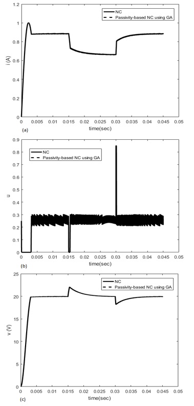
The results at generation 0 are: v=0.6563, v=0.8349, v=0.6399, v=0.3271, v=0.275, v=0.2164, v=0.2794, v=0.2528, v=0.711, w=0.0821, w=0.2998, w=0.1112, . The optimal results after tuning the parameters using GA are as follows: v=0.646, v=0.633, v=0.639, v=0.394, v=0.736, v=0.326, v=0.52, v=0.077, v=0.21, w=0.05, w=0.299, w=0.111, J=50910. Stop at generation 51. The best chromosome is 1. The cost function is illustrated in Figure 11. When R changes, the results of the passivity-based neural control using genetic algorithm is illustrated in Figure 12 and Table 7.
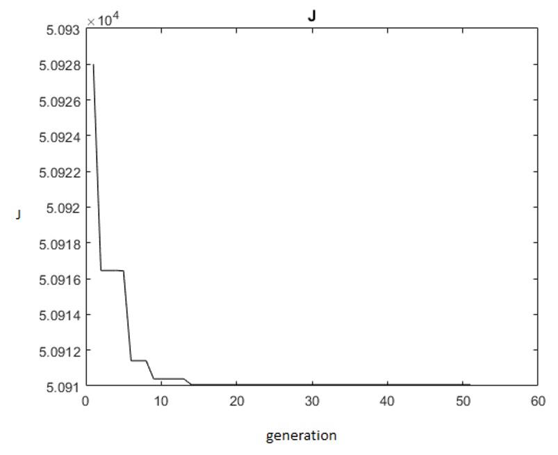

Figure 12 is the simulation results of passivity-based NC without GA when R changes. Figure 12 shows the current i, the control input u, the capacitor voltage v and the load resistor R. Figure 12 shows that at t=15 ms, when R is increased to 40 , the inductor current i is equal to 0.665 A. At t=30 ms, when R is decreased to 30 , the inductor current i is equal to 0.885 A. The settling time is equal to 3 ms. Figure 12 shows that at t=15 ms, when R is increased to 40 , the capacitor voltage v has the value (V) of 2.022 V. The settling time is equal to 2.8 ms and v is equal to 20 V. At t=30 ms, when R is deceased to 30 , the capacitor voltage v has (V) of 1.873 V and v is equal to 20 V. The settling time is equal to 2.8 ms. The value of IAE is 0.0482.
Genetic algorithm is integrated into a neural controller and adjusts optimally the weights of the neural network such as v, v, v, v, v, v, v, v, v, w, w and w. The value of q has influence to the inductor current i and decreases the settling time, 3 ms. The value of q has influence to the capacitor voltage v and decreases the settling time, 2.8 ms.
The results show that compared with NC without GA, the proposed passivity-based NC using GA has shorter settling time when R changes. It has smaller value of when R is increased to 40 . However, the NC without using GA has smaller value of IAE. The comparison results are described in Figure 13 and Table 7.
The capacitor voltage v of the NC without GA and the passivity-based NC using GA with q1=1, q2=1 when R varies.
|
Controller |
Increasing (+10 |
Decreasing (-10 |
IAE | ||
|
|
ts (ms) |
|
ts (ms) | ||
|
NC without GA |
2.10345 |
9.2 |
1.847 |
9.2 |
0.0478 |
|
Passivity-based NC using GA with q1=1, q2=1 |
2.022 |
2.8 |
1.873 |
2.8 |
0.0482 |
Conclusions
In this paper, the passivity-based neural control using genetic algorithm for a DC-DC boost power converter is proposed. The equilibrium point at origin of the plant (6) is asymptotically stable. The neural network performs the passivity-based control law. The simulation results of the passivity-based neural control using genetic algorithm and the results of the NC without using GA are done with Simulink in MATLAB.
The simulation results of the passivity-based neural control without using GA are done when the desired voltage V, the input voltage E and the load resistor R change. The results of the NC without using GA show that the capacitor voltage v is kept at the desired value. The results of the passivity-based NC using GA are performed when the input voltage E and the resistor R vary. The weights of the neural network are adjusted optimally using genetic algorithm with decimal encoder. The simulation results of the passivity-based neural control using GA show that the capacitor voltage v is kept at a desired value V. Genetic algorithm is integrated into a neural controller and adjusts optimally the weights of the neural network such as v, v, v, v, v, v, v, v, v, w, w and w. The value of q has influence to the inductor current i and decreases the settling time. The value of q has influence to the capacitor voltage v and decreases the settling time.
The results show that compared with the neural control without GA, the proposed passivity-based neural control using GA has shorter settling time and smaller value of IAE when E changes. Moreover, the passivity-based NC using GA has smaller value of than the NC. The results show that compared with NC without GA, the proposed passivity-based NC using GA has shorter settling time when R changes. It has smaller value of when R is increased to 40 . However, the NC without using GA has smaller value of IAE when R changes.
The paper has limitations such as the assumed circuit parameters. Future research will explore a practical real-time experiments.
ACKNOWLEDEGMENT
We acknowledge the support of time and facilities from Ho Chi Minh City University of Technology (HCMUT), VNU-HCM for this study.
ABBREVIATIONS
PBC - passivity-based control
GA - genetic algorithm
NC - neural control
COMPETING INTEREST
The authors agree with the manuscript of the paper and have no conflict. The paper has not been submitted in the other journal.
CONTRIBUTION OF THE AUTHORS
Hoai Nghia Duong is the corresponding author. He guides the research idea, gives suggestion to the paper so that Minh Ngoc Huynh corrects the paper. He gives the final agreement for the paper to submit.
Vinh Hao Nguyen is the author. He guides the research idea, gives suggestion to the paper so that Minh Ngoc Huynh corrects the paper.
Minh Ngoc Huynh is the first author. He writes the manuscript of the paper and does simulation. He corrects the paper according to Hoai Nghia Dương’s and Vinh Hao Nguyen’s suggestion and the reviewer’suggestion.